I haven’t shared much about my modular synth, but I really should. I’ve created several custom synth modules – even designing PCBs and custom 3D printed faceplates for them. The circuit design is also my own although heavily inspired by the very helpful synth DIY community. There’s only so many ways to build an Arduino-based utility module, anyhow.

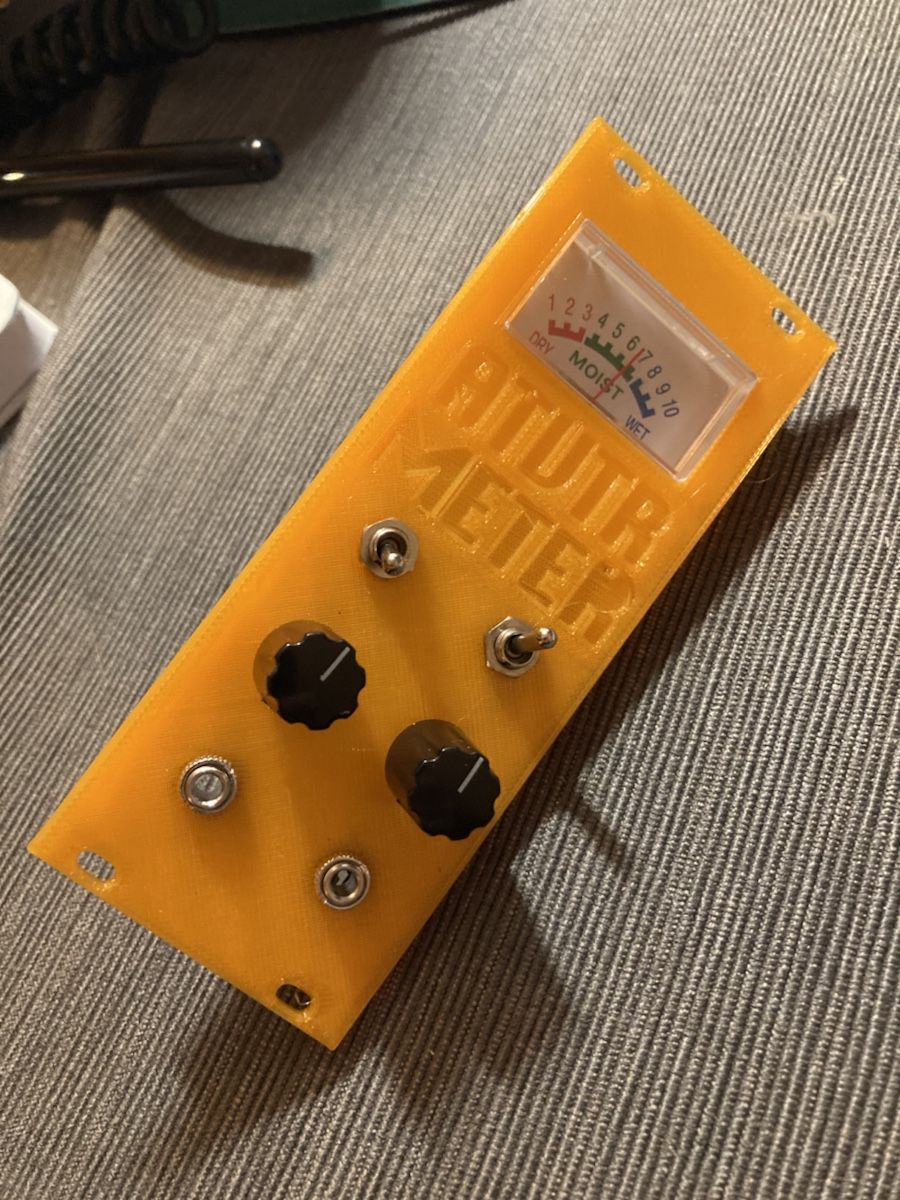
This module hasn’t been finished but the front panel is pretty much complete. In addition to visually displaying a signal on the meter, it also has an “attenuverter”. This is a circuit which multiplies the input by a manually adjustable value between -1 and 1. This can both attenuate and invert the input signal – thus the portmanteau attenuverter. It’s a handy capability for modifying control voltages like and LFO or ADSR. I’m adding the ability to add an offset to the output, which allows you to move some control voltage up or down by some bias amount in addition to attenuating it.
I think I’ll also add a few modes to the meter such as a low value mode for voltages between -5 and 5, a high value mode for voltages between -10 and 10, and something like a VU meter – which looks at the average peak value. These have all been breadboarded in the past but I need to combine them all into one circuit and make a PCB for it.
The front panel printed out correctly on the first shot – even the snaps that hold the meter in place work great. That’s satisfying.

I need to find a typeface more suitable to printing though. Anyone have recommendations? Drop me a line. I’d like something that doesn’t have floating regions unconnected on the first print layer. Those seem to get messed up when I use cheap filament because of adhesion issues. You can see that in the photo in the case of the second capital R.