I have a few prototype Eurorack modular synth modules in the works. I tend to get them working well enough to be musically interesting and then move to work on the next prototype. It’s not because I don’t plan on finishing them – it’s more that all the biggest questions are answered and I want to move on to the next prototype and answer whatever questions it is trying to answer.
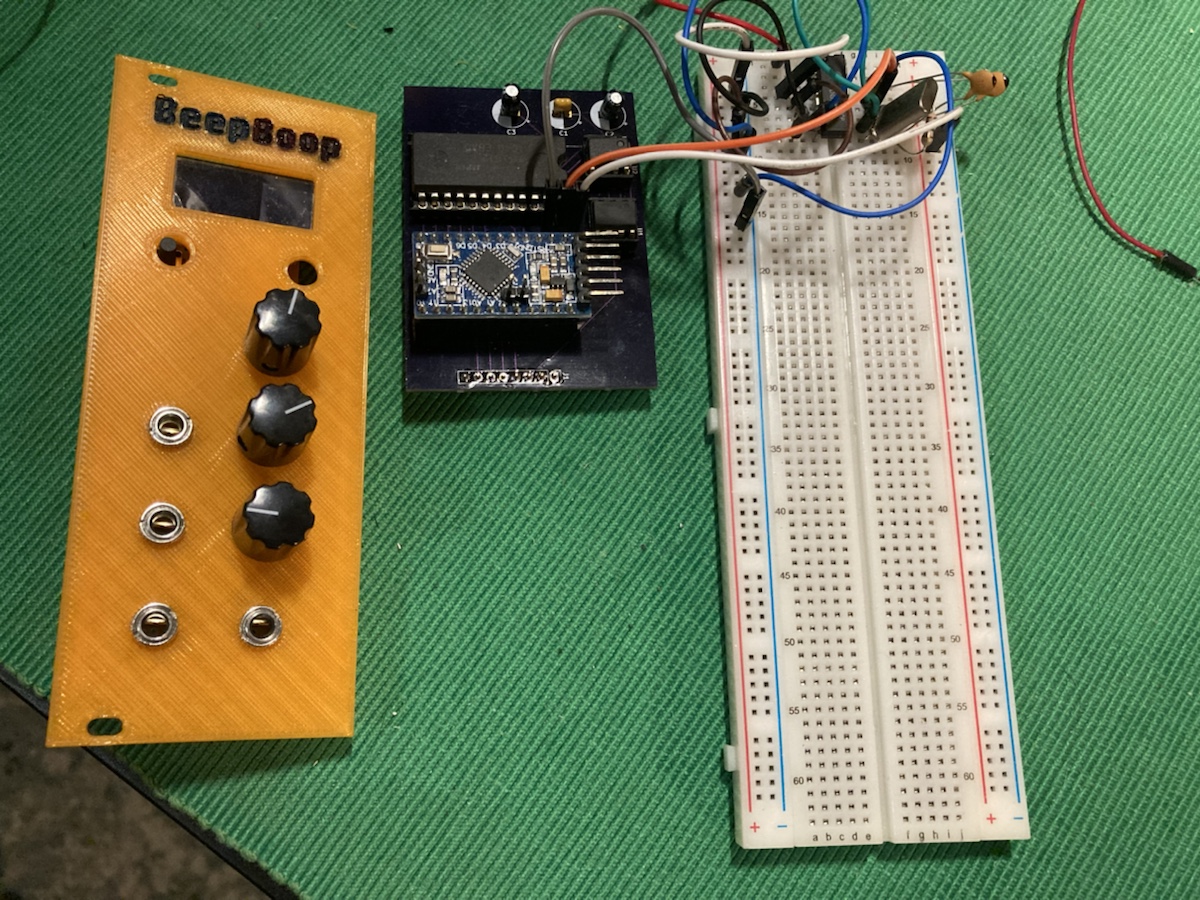
This module is based around the Yamaha YM3812 chip, also known as the OPL2. You might know it as part of the capabilities of the AdLib and original Sound Blaster sound cards. Think of the classic sound of the Doom soundtrack – that’s coming out of a YM3812 (emulated or otherwise).
But you can do a lot more than what you hear on the Doom soundtrack – even though I’d be fine if that was the limit of it’s sonic capabilities. FM synthesis is “weird” in the way it can produce wild sounds that are very hard to produce with subtractive synthesis. As an added bonus, the YM3812 has multiple symmetrical channels and is this capable of impressive polyphony. One module isn’t just one voice – it’s 6. Also it has a drum synth mode… It makes sense that it is so capable if you think about all the great PC game soundtracks made with one, but it isn’t what you’d expect to be coming out of a single modular synth module.
The Problem
In the modular world, you tend to break apart and de-integrate as much of the synth chain as possible. This is so you have the freedom to reconfigure the synthesis signal path in wild and fun ways. So a module with not only a complete voice but six complete voices is swimming against the current in how you typically design these things.

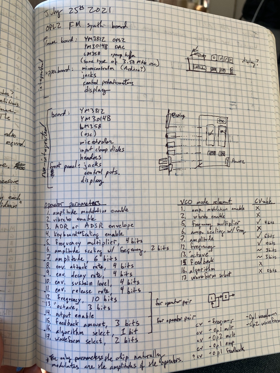
One outcome of such a non-modular module is the matter of the number of possible parameters available. Typically a module might have 1-4 inputs and 1-2 outputs. That’s a gross simplification but gives you an idea of the majority of signal complexity involved. A single channel of a YM3182 has about 16. And then you have 6-8 copies of those – each voice can be configured more or less independently. So we’re talking hundreds of possible inputs.
It has one output.
So on the face of it, this is a bad match. And therein lies the hypothesis of this design. “How can you adapt a YM3812 to the modular synth design norms?” How do you make it understandable to someone thinking in terms of fairly straightforward signal chains? How do you present the configuration of a YM3812 so it matches the mental model of someone used to something like the Behringer Neutron?
A Lone Voice
I can’t do anything about the output space. There is literally only a single pin for the output and there isn’t any access to the individual voices. So right off, I decided that this prototype would be a single voice. That might seem wasteful, but I can use the other voices to “mirror” the main voice to fill it out by slightly detuning them or by playing notes related by harmonics such as octaves or triad chords.
That also reduces the input space. We’re down from hundreds to a dozen or so inputs if we’re only treating this as a single voice. Some existing designs stop there, but I wanted to go further.
Time Variations
There are broadly two types of inputs to a voice: time varying and time invariant. The time varying inputs configure, for example, the way the amplitude of the sound changes over time. In a modular synth, input like this are controlled by other modules. So I decided to discard all time-varying parameters. Parameters like the amplitude of the voice would be modified externally using voltage controlled amplifiers (VCA) just like you would do with a standard modular signal path.
This reduces the input space by half. We’re looking at about 6 inputs. That isn’t bad – there are definitely synth modules with 6 inputs. But I wanted to go further.
Digital Zippers
The YM3812 is a digital chip. All of the OPL series of synth chips are. This is what made them such a great product for Yamaha. It was easy to make a digital chip out of silicon so they could produce the entire sound path out of a handful of parts that would take thousands of separate analog components to replicate. And because it’s digital, it’s very easy to use in a PC sound card. The CPU just sets the input registers of the chip and away you go.
In a modular synth, all of the patch paths are analog: continuous time varying signals between about -10 to 10 volts. To adapt these kind of signals to the YM3812, I would need to digitize them using an analog to digital converter (ADC). But there’s a problem here too – what sort of digital resolution should I use? If I use too low a resolution, the continuous varying signals end up being converted to broad, stair step patterns. It means your smooth subtle varying input gets turned in to sudden chunky sound changes. People call this effect “zippering” because it can cause a sound similar sound when a parameter moves through those discrete stair step values. That isn’t intrinsically bad in the world of analog synths, but you’d like to at least have the option to avoid it.
Some of the input parameters of the YM3812 have a very limited range of possible input values. As an example, the strength of the feedback from one internal voice generator to itself is controlled by just three bits. That’s only 8 possible values! That does not map well to a 20v swing input.
So I took all the parameters that did not have enough bits of configuration available to be used with an analog input off the table. I would still have them accessible, but through manual switches and control knobs. They’d be more for setting the broad mode of the voice, not for use inside the time of a single note playing. That removes a handful more inputs from consideration. In fact, you’re down to only four. That is a completely respectable number of inputs for a synth module. But I wanted to go further.
Getting Rational
One of the interesting things about FM synthesis is that a lot of the timbre results from the mathematical ratio between the different frequencies of the oscillators involved. In the YM3812, each oscillator has 12 possible frequency multipliers to aid in defining these ratios. So while there are only 12 values for a given oscillator, there are 144 combinations between the two oscillators of each voice. Twelve steps isn’t enough for an analog input but 144 is fine. So my final reduction was to combine the two ratio inputs into a single input.

And that leaves us with just three inputs: one that controls the frequency of the voice, one that controls the amount of mixing between the two internal oscillators, and one that controls the ratio between the oscillators. To put it another way: one controls the pitch and the other two control the timbre. That sounds like a perfectly understandable module. It is still more integrated than you would see in a traditional module where the timbre modification would occur in a separate module (or sets of modules), but it is much closer.
And there you have how I arrived at the final design of the prototype. All other design considerations stem from the decision of which inputs to use: the physical layout, the specifics of how signals map to sound changes, the size of the module, etc.
There are a lot of details I’m glossing over here, and I’ll talk about them more in future articles.