Aka “ADDDA” or “AuDiDeDrAr” or “aww dee dee drawer” or “A3DA”
I’ve had this idea bouncing around in my head that you could use 1-bit wide DRAM as a delay line if you simply counted up through it’s addresses, reading and writing as you go. 1-bit wide DRAM like the M3764 have separate pins for Data In and Data Out which makes the read-and-write method easier.
The light bulb moment was coming across an old post on diystompboxes.com where one commenter provides a short snippet of code to do a Delta-Sigma analog to digital converter using the Arduino’s analog comparator pins. I had planned to do this purely in software by using the normal ADC pins and then calculating the Delta myself. But the built-in comparator makes this dead simple!
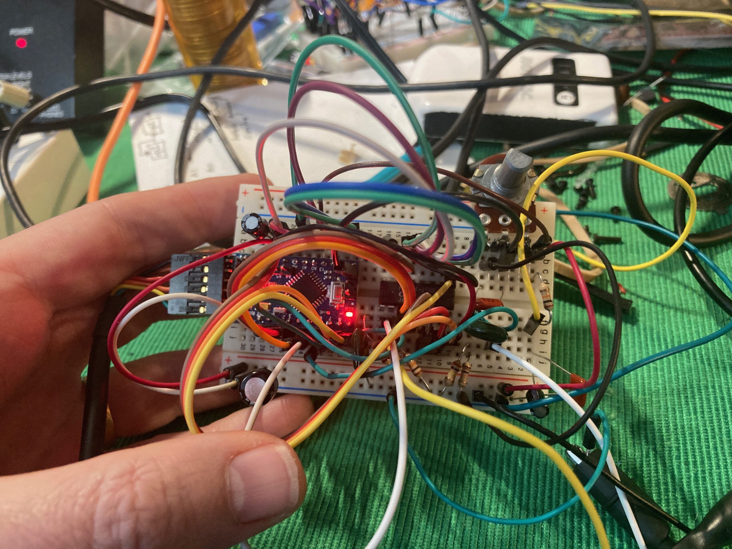
So armed with an easy way to generate a one bit wide data stream from an analog signal, I went about hooking up the DRAM chip to a clone Arduino Pro Mini. There are quite a few “test a DRAM chip with an Arduino” projects out there, but the datasheet for the OKI chip has good timing diagrams that give the jist of what you need to do. DRAM has a shared set of address pins for the row and column you’re selecting, which you can think of as two halves of the full address. To get those halves in, you put the row on the address lines and strobe the /RAS pin. Then you put the column on the address lines and strobe the /CAS pin. Then your data is on the Data Out pin. Writing involves putting the data you want to write on the Data In pin and strobing the /WE pin after you strobe the /CAS pin. That’s really all there is to it. You’ll see that there are some short cuts you can take to speed up access, like only setting the row once for any number of columns you’d like to access. You can also read the Data Out pin right before writing new Data In. I do both of these in my implementation to increase the sample rate.
To start out, I did everything very simply, using the built-in Arduino functions to make it easy to read and understand. I then measured the performance of the main loop by looking at the Sigma-Delta signal’s minimum change period. This gave me a base line, and then I systematically went through the code swapping out the built-in functions for faster implementations one by one, measuring any increase in performance. If a change didn’t lead to any improvement, I wouldn’t commit it. Instead I’d commit a comment that I’d tried it. In retrospect, it’d have been better to use git revert so I had a better history of what I specifically tried.
Doing this I was able to improve the performance of the DRAM access by a factor of about 16. The original version took 8 seconds to cycle through the entire memory and the final version took about 500ms. My commits show the improvements, although I realized later I was measuring the wrong signal! It was at least indicative of the improvements. All of the timing in this project has a lot of jitter due to the many different possible code paths with no attempt to balance them out.
In the end, the DRAM /WE pin is the best measure of how often you’re writing to the DRAM. It is at about 139 khz. I measured the actual audio delay produced by the system using my oscilloscope and it is about 480 ms at it’s longest. Those two numbers agree:
1 second      | 64*1024 samples           seconds
--------------|----------------- = 0.471 ---------
139 k samples | 1 buffer                  buffer
I’m new to working directly with delta-sigma converters, and after reading a few pages about it this morning, I’m not sure what I’ve built is exactly a delta-sigma converter at all!
My current understanding is that 139 khz sampling rate (F) means a Nyquist frequency (F/2) of 69.5 khz regardless of the type of converter used. I found a paper by Aziz, Sorensen, and Van der Spiegel from 1996 describing how delta-sigma converters work, and it gives some equations.
Letting the oversampling ratio, f_s / (2 * f_b) = 2^r …
[Therefore] every doubling of the oversampling ratio i.e., for every increment in r, the SNR improves by 9 dB, or equivalently, the resolution improves by 1.5 bits.
Aziz, P., Sorensen, H., & Vn Der Spiegel, J. (1996). An overview of sigma-delta converters. IEEE Signal Processing Magazine, 13(1), 61–84. https://doi.org/10.1109/79.482138
f_s -> sampling frequency
f_b -> signal bandwidth
r -> oversampling

f_s / ( 2 * f_b) = 2^r

f_s / 2^r = 2 * f_b
f_s / (2 * 2^r) = f_b
f_s / 2^(r+1) = f_b

139e3 / 2^(r+1) = f_b
r = 0, 139e3 /  2 = 69.5 khz,  Nyquist sampling
r = 1, 139e3 /  4 = 34.7 khz, +1.5 bits
r = 2, 139e3 /  8 = 17.3 khz, +3.0 bits
r = 3, 139e3 / 16 =  8.6 khz, +4.5 bits
r = 4, 139e3 / 32 =  4.3 khz, +6.0 bits
r = 5, 139e3 / 64 =  2.2 khz, +7.5 bits
Those numbers would suggest a fairly lofi device. And certainly what I have running on my desktop is by no means producing quality audio. But it also doesn’t sound that bad? I’m losing a bit in my calculations because I should be counting the “single bit” of the comparator. If we take that bit and then work it backwards…
f_s / (2 * f_b) = 2^r
total_bits = 1.5 * r + 1
8 bits = 1.5 * r + 1
r = 7 / 1.5 = 4.667
139e3 / 2^4.667 = 139e3 / 25.398 = 5.47 khz
So the system is operating at 8 bits up to a bandwidth of 5.47 khz. That sounds about right. What happens if I add more features and reduce the sampling rate to 100 khz?
100e3 / 25.398 = 3.94 khz
What happens if I find some optimizations and increase the sampling rate to 200 khz?
200e3 / 25.398 = 7.87 khz
Someone check my math.