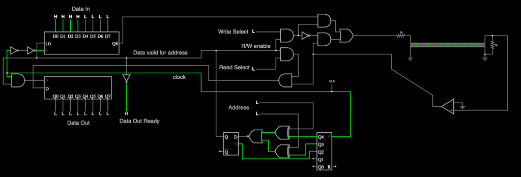
I was getting bent out of shape that I needed to somehow reconstruct the system clock out of the data stored inside a delay line. But fooling around with an old discrete delay line simulation in a circuit simulator by replacing the giant stack of flip flops with a proper length delay line shows that I don’t need to be too concerned
As long as
- The delay line stays a constant delay length in terms of time (dubious)
- The system clock stays a constant speed (actually very easy because amazingly stable crystal oscillators are trivial nowadays)
Delay lines varying in time is
- Highly probable with any sort of rotating media (magnetic drums, etc)
- Less likely for “solid state” delay lines such as acoustic torsion delay wire.
- Unknown for any other technology (tape loops?)
For rotating media or tape loops, it would probably be good to assume they require a second timing track. It’s somewhat of a “waste” of media density, but you should only need one per media – so one track on a drum or one track on the tape. You can have as many other tracks as you can cram on there.
For the more stable media, where the main drift is due to temperature, there could be some type of calibration mode where a signal is put into the delay line and then compared to the current clock speed. The clock speed could then be adjusted to match. This could even be automatic – perhaps something you would perform once on startup, and then once again when the machine is up to operating temperature. Of course any thing that is temperature dependent is probably best handled by installing a heater and keeping it at a steady 100degF (or whatever) no matter what.
